Radio Remote Controlled Robotic Arm
|
During my first year of graduate school began to purchase electrical equipment for my apartment with the little amount of spare money I had. I purchase a small multimeter, helping-hands, temperature controlled soldering station, a solder sucker and wick, and a few other tools. I decided the first project I wanted to work on was creating a radio controlled robotic arm from an RC car I had lying around from when I was younger. I decided to program the whole robot using an Arduino Uno microcontroller. The video on the right shows the fully functioning program. At this point, I haven't had enough time to construct the rest of the arm, but the program itself is finished and awaits the other 4 servos to be attached.
|
|
||
Step 1: I started off by designing my own shield for the Arduino board so I could solder all my circuitry onto it.
|
|
|
|
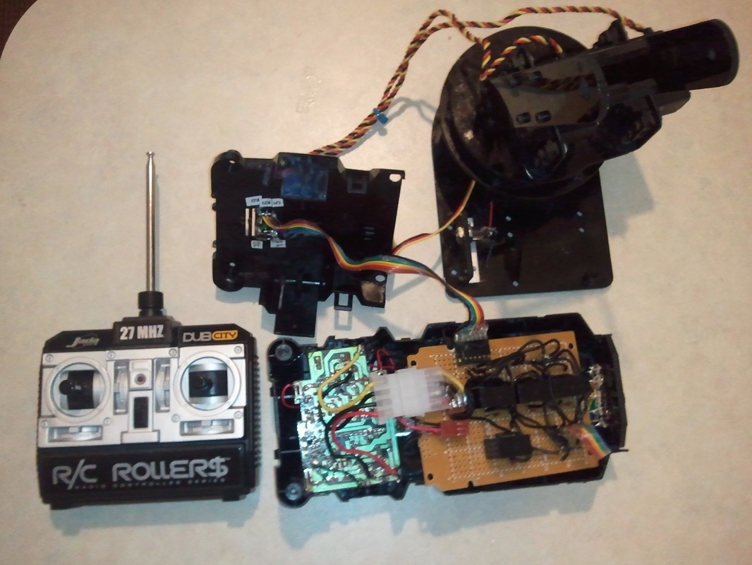
Step 2: The next step was to take apart a RC car that I had lying around. I had a working 27MHz controller and removed a 27MHz radio receiver from the car. I also decided to keep the black casing of the car as the base for my robotic arm to store all of my electronics.
|
|
|
|
Step 3: I removed one section of the plastic casing using a dremel tool and cut a hole in the frame to mount a switch that would be used to turn the robot on and off. As you saw from previous pictures, I could use the rechargeable battery from the RC car to power the robotic arm and could use the battery compartment on the bottom of the car frame to store the battery pack. I soldered my own wires to the metal contacts that touched the battery terminals and also mounted the radio receiver into the plastic casing. Additionally, I added a connector cable to the battery terminals to connect to the shield of the Arduino for power. The bigger, 4 pin connector, was used to transmit the signals from the receiver.
|
|
|
|
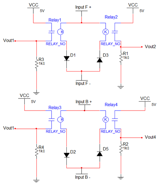
Step 4: Next, I had to figure out how to get the signals from the receiver to the Arduino. The receiver was designed to output +/- 5V to the front and back wheels (Input F and Input B). I did not have any schematic on how the receiver work and didn't want to attempt to pin off signals from the board itself. I figured a much easier way was to build a quick circuit to read off the motor signals. The first problem is that the Arduino can only accept input from 0 to 5 V. In order to solve this problem, I used diodes to determine whether each Input (F or B) was supplying +5, 0, or -5 volts. When supplied with 0 volts, the relays to not operate do to them being normally open and therefore not completing the latch pulldown circuit connected to each Vout pin. Note that there should be some type of resistance in series with the relay and diode to limit the current flow, though mine seemed to work fine without the need of additional resistors in series. The way the circuit works is explained as follows.
For example, when Input F is +5 volts, D1 is short and Relay 1 closes and sets Vout1 high. When Input F is - 5V volts, D2 is short, while D1 is open and closes Relay 2 which sets Vout2 High. From here the HIGH/LOW inputs were used to control the robotic arm.
For example, when Input F is +5 volts, D1 is short and Relay 1 closes and sets Vout1 high. When Input F is - 5V volts, D2 is short, while D1 is open and closes Relay 2 which sets Vout2 High. From here the HIGH/LOW inputs were used to control the robotic arm.
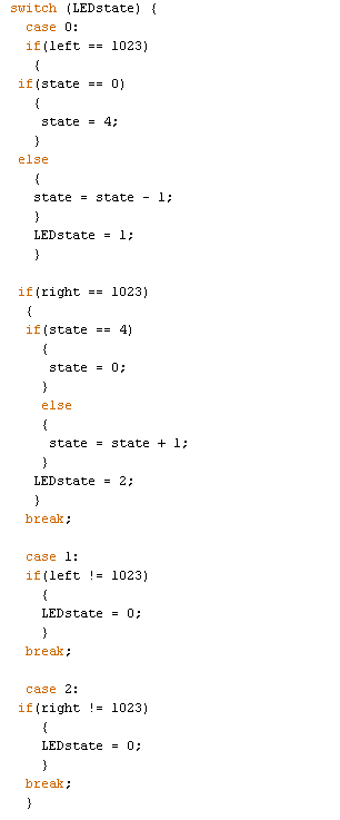
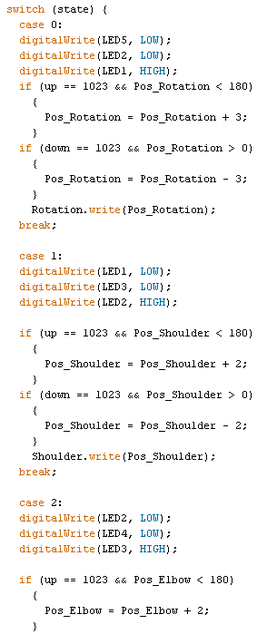
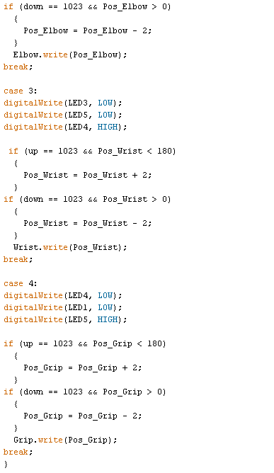
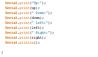
Step 5: The circuit was soldered to the shield and tested using the serial monitor in the Arduino IDE. I could see when each direction on the controller was pressed. The next problem is how to control a 5 point robotic arm with only 2 single direction control sticks. I decided that I would use one stick to toggle between each arm joint and the other stick to control the direction of the joints rotation. To know when each joint was activated, I created an LED array to show which LED arm joint is active. I also attached ribbon cables for servo motor inputs and attache 3 pin headers to the frame so servo motors can easily be attach and removed. To avoid having to take the robotic arm apart constantly, I added an external USB port to the back of the robot that connects directly to the Arduino for easy programming.
|
|
|
|
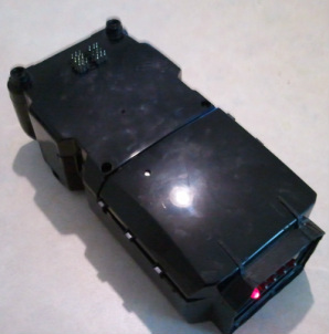
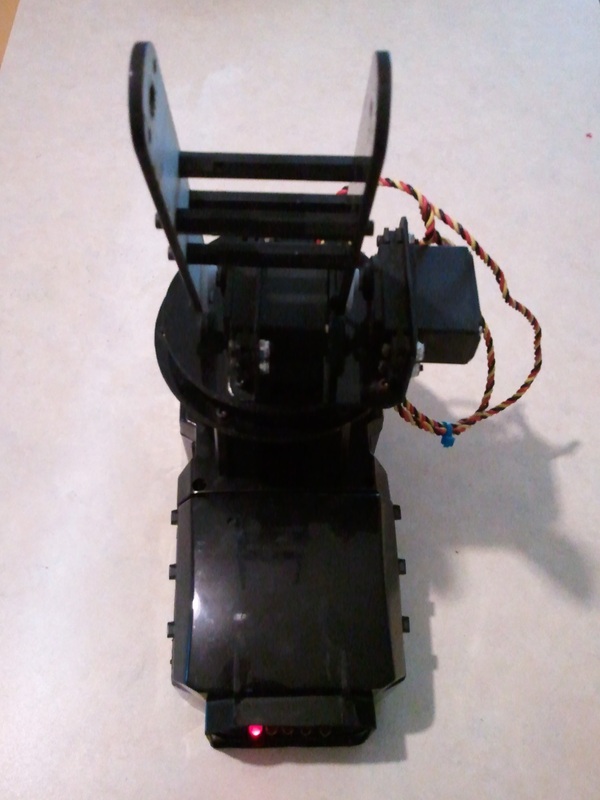
Step 6: The final step was to make sure everything fit inside the box and worked properly.
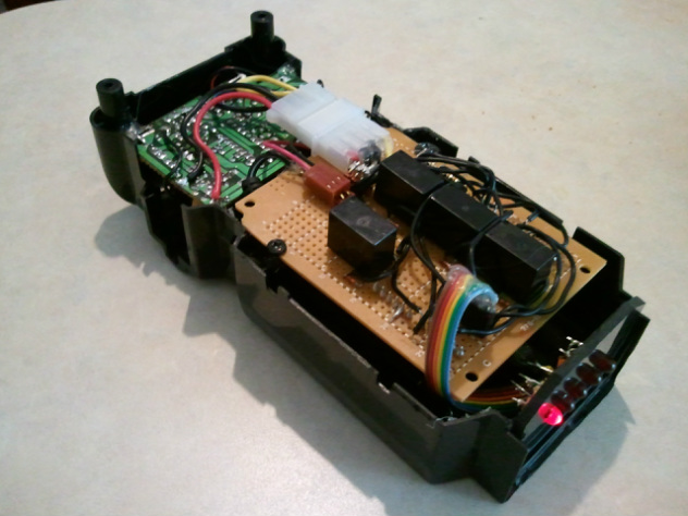
I made sure to test it before closing the box and screwing it together.
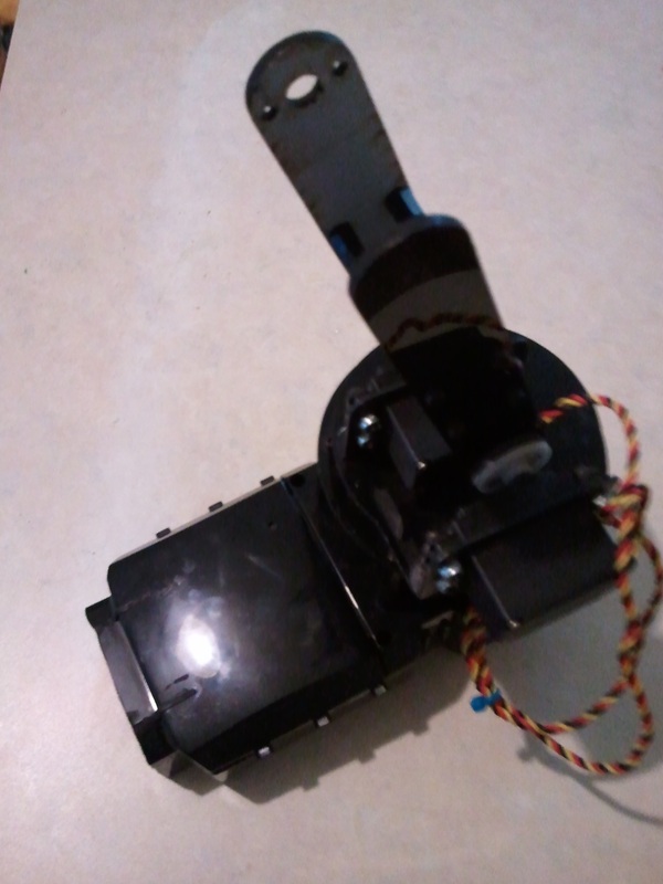
Step 7: The step which I am at now is to finish the construction of the arm itself. The robotic arm itself is fully functional and was a great learning experience.
|
|
|
Goal
The final arm should look very similar to the example shown below. When I finish the design, I will update this post.
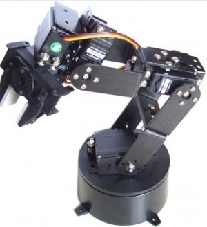
http://www.dfrobot.com/wiki/index.php?title=6_DOF_Robotic_Arm_(SKU:ROB0036)
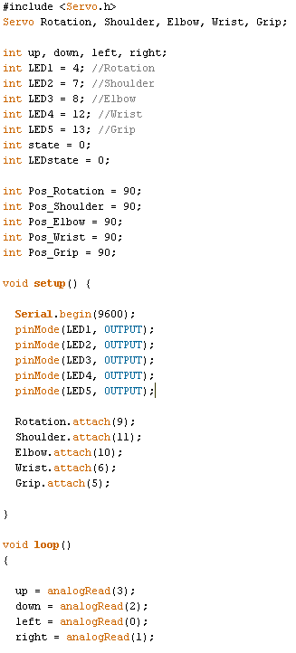
Code
The arduino file is downloadable at the top of this page.
|
|
|
|
|
|
