Building a Micromouse for an IEEE Student Activities Conference (SAC) Competition
I have worked with the student chapter of IEEE for several years and was the Vice President in my senior year of my undergraduate degree. Being a graduate student doesn't give me as much time to attend events, but I did offer to help the undergraduate team design and build a micromouse for the SAC competition. If you are unsure what a micromouse is, it is a small robot that can solve a maze using some type of maze solving algorithm. The goal of the competition is to solve a maze as quickly as possible. As a group, we decided to use an Arduino Uno microcontroller to control the robot.
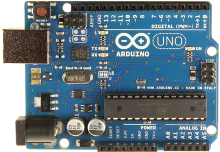
http://arduino.cc/en/Main/ArduinoBoardUno
A basic micromouse would use continuous servo motors to drive the robot. Additionally, servo motors are much easier to control and are able to make accurate movements, but they tend to be much slower than DC motors. We decided to focus more on speed. Our design used 2 dc motors that came in a kit. The kit included mounting brackets, wheels, and all mounting screws needed.
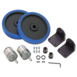
http://www.parallax.com/
To drive these motors we used a DC motor shield designed to work with an Arduino Uno. It allows us to control speed, direction, and frequency of the motors. With the shield we chose, we can control up to two DC motors at once. Both the Arduino and the motor are powered by a 9v battery and are connected together using 9v battery caps.
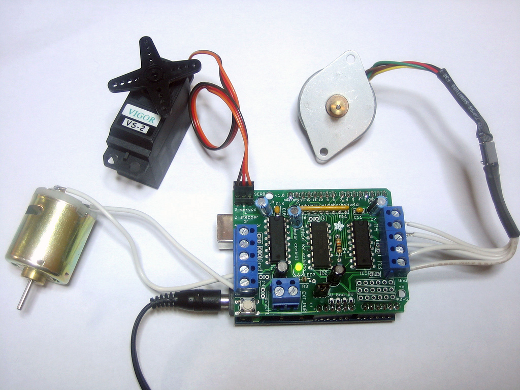
http://www.adafruit.com/
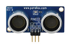
Ping sensors were used to tell the robot where was and give feedback to control the speed of the motors. The ping sensor sends out a ping and measures how long it takes to come back. Based on the time and the speed of the sound wave, it can determine how much distance there is between the sensor and an object. In our case, it detects the maze walls.
http://www.parallax.com
Conventionally in these designs, a single pin sensor is used and is mounted onto a standard servo. The servo motor would then look left, look right and then look straight ahead and find direction to continue in. This takes a lot of time since the servo motor must rotate in several directions before making a decision to move. By using three sensors, we reduced the time it took to make decisions and to determine which direction to take.
Constructing the Frame
In order to reduce the cost of the project and to enter into the "custom built" category of the competition, (competitors could also purchase an entire micromouse kit that provided step by step instructions to build it) I custom built a frame for the micromouse.
Step 1: I started with some scrap plexiglass I had lying around and cut a rectangle piece from it. I then drilled holes and mounted the two dc motor brackets. From here I started to heat up and shape the frame as I pleased.
Step 1: I started with some scrap plexiglass I had lying around and cut a rectangle piece from it. I then drilled holes and mounted the two dc motor brackets. From here I started to heat up and shape the frame as I pleased.
The first goal was to create an area where the motors could be housed.
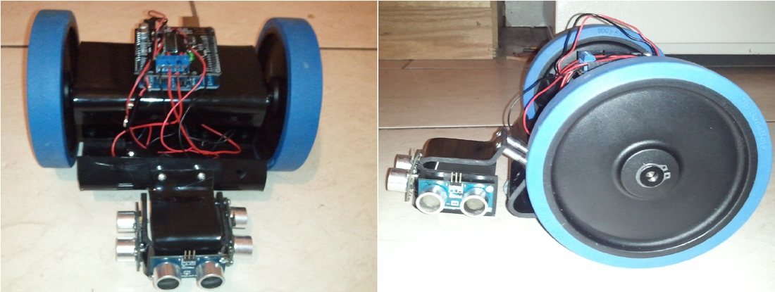
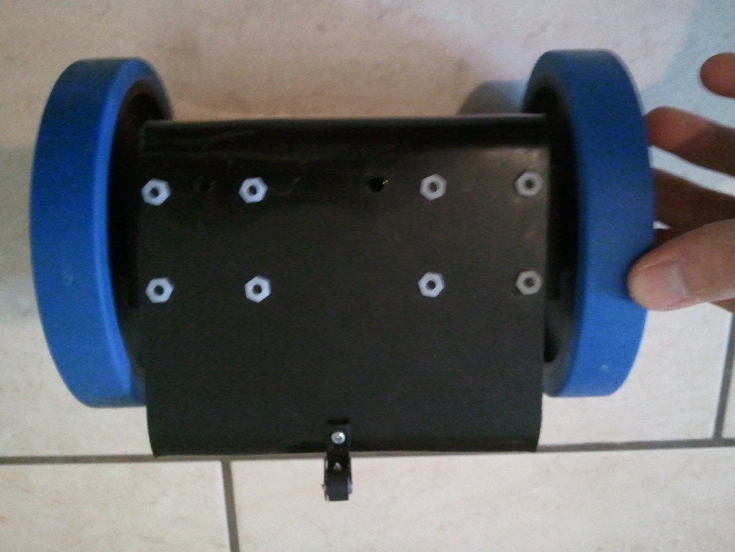
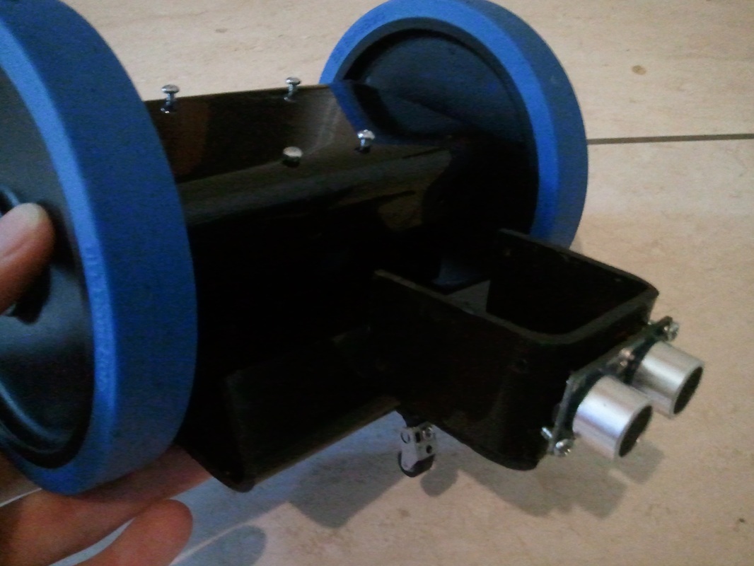
Step 2: I then mounted the motors onto the brackets and mounted the wheels onto the motor shafts. I drilled holes and placed screws in the top where the microcontroller and motor shield would be mounted. I curled the front of the frame upward so I had place to mount the ultrasonics and small guiding wheel in the front. The small wheel was taken from a cassette player.
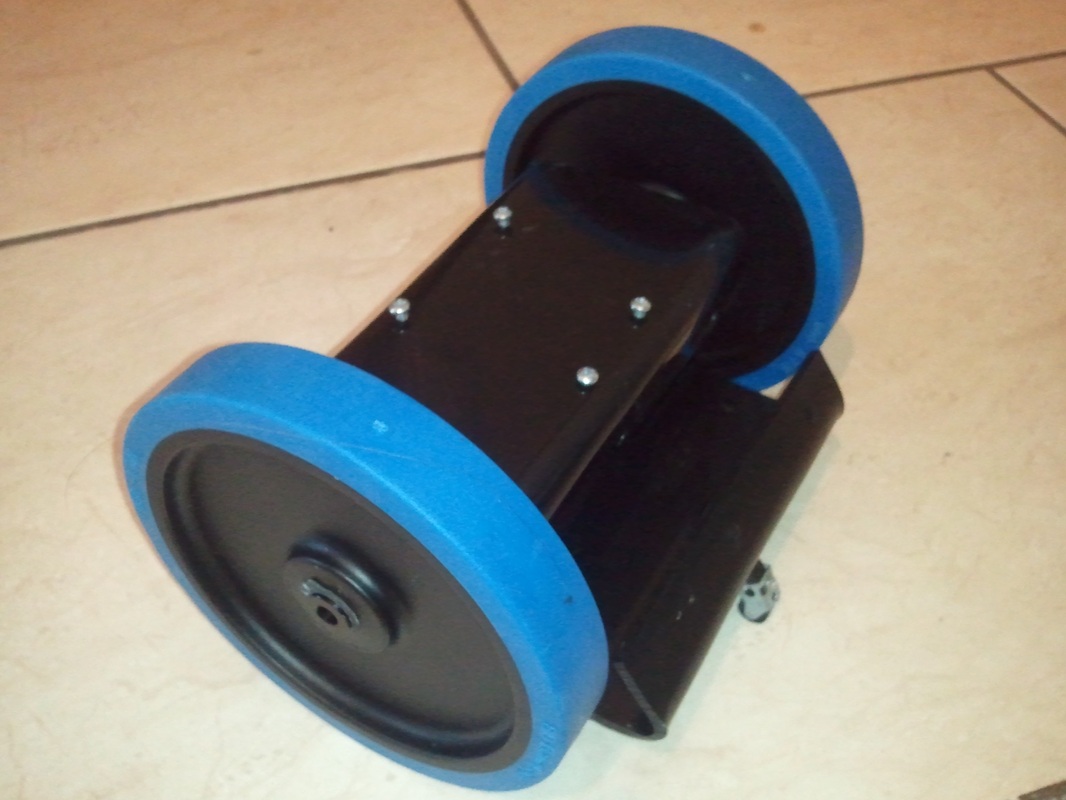
Bottom view.
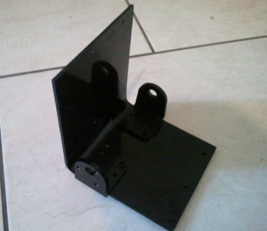
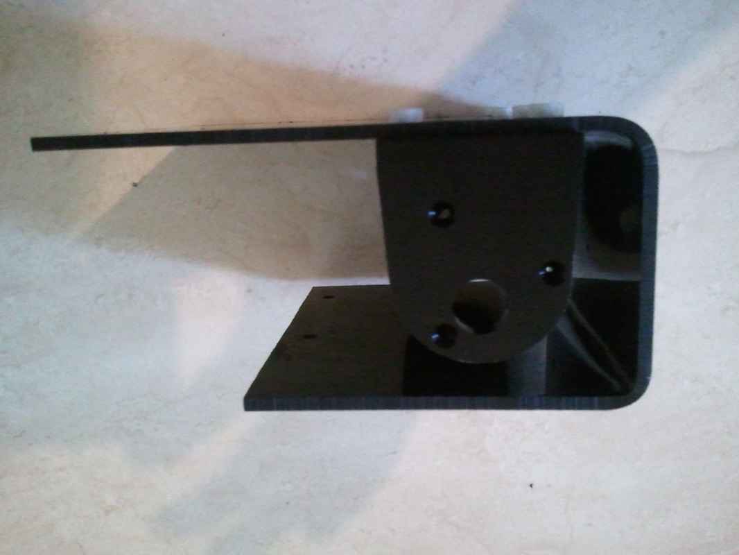
Step 3: Using the leftover scraps I designed a mounting bracket for the three ultrasonics. I designed it much like a cardboard box is designed keeping in mind how I would bend each side. This first design needed to be modified later due to the ultrasonics being too high and pinging above the mazes wall height limit. You will see in later pictures that the mount was flipped so the sensors were closer to the ground.
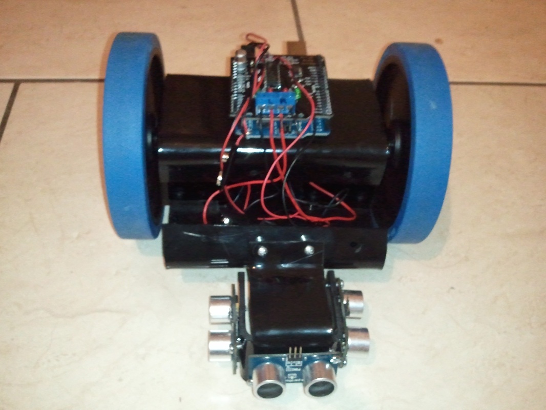
Step 4: Once the frame was complete, all of the hardware was mounted and wired. Each dc motor has a positive and negative terminal designated on the dc motor shield. One 9v battery cap was connected to the voltage source input of the motor shield which was used to drive the dc motors. Another 9v battery cap was soldered to a barrel cable that could be plugged into the Arduino Uno for power. We later used replaced the 9v batteries with an RC car battery pack that was capable of recharging to save time and money. Now that the micromouse was build, the next step was to program it.
Programming the Micromouse
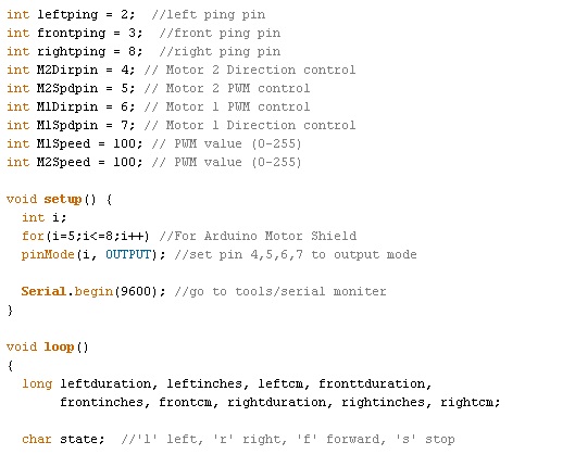
The programming was done in the Arduino IDE. I started with some base code provided with the dc motor shield and adapted the code from there. The code was broken up into several portions. The setup portion sets all the pins that are being used for both the dc motor shield and the ping sensors.
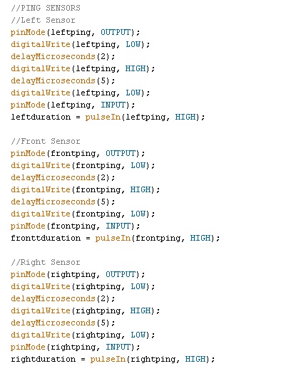
The ping sensor code was acquired from the provided examples in the Arduino IDE help file and adapted to work with 3 ping sensors. The sensors ping in a sequence, one after the other, and do this repeatedly.
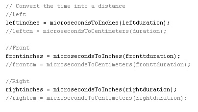
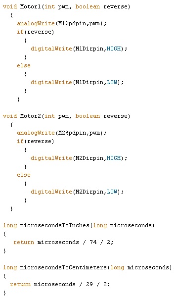
The time it takes for the ping to be sent out and bounce off of an object is converted using a function that converts the duration into inches.
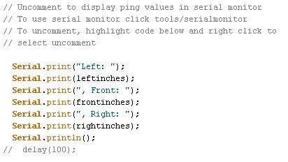
For trouble shooting, I wrote a small portion of code that can be uncommented and ran as part of the program. When the code is ran, the built in serial monitor of the Arduino IDE can be used to see the live distances each of the ping sensors is reading. A delay can be used to slow down how fast the returned value is refreshed.
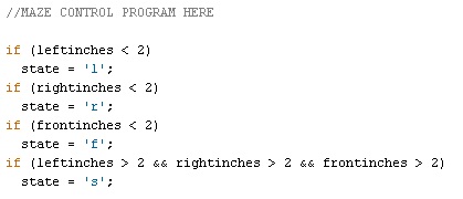
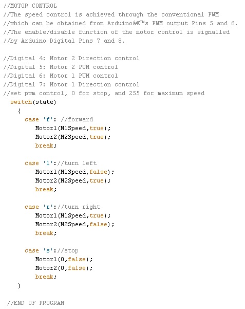
This section of code was left for the undergraduate students to complete. I wrote a basic program to confirm that all of the hardware was communicating properly with the software. As you can see, the program is set up so that the current state is updated with the characters "l", "r", "f", or "s" which stand for left, right, front, and stop. These commands can be used to control the robot and tell it which direction to go. It was up to the undergraduate students to determine what type of maze solving algorithm they wanted to use.
The motor control was done using a case statement controlled by the state characters discussed above. This made controlling the robot easy be simply sending the direction they wished the robot to drive in. The speed can also be updated at anytime.
Here are the function that get called on to send the correct control signals to the dc motor shield.
The undergraduate team programmed a maze algorithm to the best of their abilities and competed in the competition. They didn't win, but they learned a lot.
Download Code Here
| micromouse.ino |
